Microfluidics and the Phase Chip:
Protein crystals are necessary in order to determine protein structure using x-ray diffraction. Typically the number of crystallization trials are limited by the availability of protein, hence
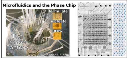
the drive to minimize sample volume. To address this problem a high-throughput, low volume microfluidic device denoted the Phase Chip is being developed. On this device different
microfluidic components have been designed, fabricated, and interconnected in order to precisely meter, mix, and store sub-nanoliter amounts of sample, solvent, and other reagents. The Phase Chip
can store thousands of sub-nanoliter drops of protein solution in individual wells and a total of 103 crystallization trials can be accomplished with 1 - 10 microgram of protein thereby
enabling high-throughput crystallization of mammalian proteins expressed in tissue culture. Additionally each sample well is in contact with a reservoir through a dialysis membrane through which
only water and other low molecular weight organic solvents can pass. Thus the concentration of all solutes in an aqueous solution can be reversibly, rapidly, and precisely varied in contrast to
current microfluidic crystallization methods, which are irreversible. Rapid reversible dialysis solves a major problem in protein crystallization, the decoupling of nucleation from growth. Using
the phase chip we will screen crystallization conditions using proteins that are not available in sufficient quantities for current techniques. The protein targets are bacterially-expressed
recombinant channel proteins, G protein-coupled receptors heterologously expressed in a mammalian cell culture system, and enzymes which produce crystals too small for diffraction.
Mapping and manipulating temperature-concentration phase diagrams using microfluidics
Lab Chip, 2010, DOI : 10.1039/b925661j (link to supplementary data).
Measuring the Nucleation Rate of Lysozyme using Microfluidics.
Crystal Growth & Design, DOI: 10.1021/cg800990k (2009).
Using microfluidics to decouple nucleation and growth of protein crystals
Crystal Growth & Design 7, 2192-2194 (2007).
Control and Measurement of the Phase Behavior of Aqueous Solutions Using Microfluidics
J. Am. Chem. Soc. 129, 8825 - 8835 (2007); DOI: 10.1021/ja071820f.
Supporting Information. Movies.
Rapid prototyping of thermoplastics for microfluidics
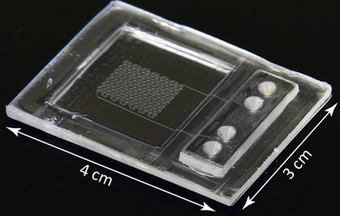
We introduce a low-cost, high yield rapid fabrication method for casting COC microfluidic chips that is appropriate for academic labs and small companies. Devices are comprised of two molded pieces joined together to create a sealed device. The first piece contains the microfluidic features and the second contains the inlet and outlet manifold, a frame for rigidity and a viewing window. The microfluidic features are patterned using a PDMS mold that itself was replica-molded from a photoresist master. Dimensional stability of the microfluidics portion of the COC device is achieved by confining the PDMS mold in an aluminium frame. The mold for the lid is CNC milled from aluminium. Sealing the COC device is accomplished by timed immersion of the lid in a mixture of volatile and non-volatile solvents followed by application of heat and pressure. Surface treatment to render the device fluorophilic is performed using dopamine in assembled devices.
Rapid prototyping of cyclic olefin copolymer (COC) microfluidic devices
Sensors and Actuators B 247 (2017) 940–949

Loading of the protein crystallization “store-then-create chip”. After surface treatment to render the chip fluorophilic, the chip is first primed by injecting a mixture of 78 vol% FC-43 fluorinated oil with 12 vol% surfactant (1H,1H,2H,2H-Perfluoro-1-octanol) using syringe pumps. Oil displaces the air and fills all the features (channels, wells and capillary valves). Air bubbles trapped in the storage wells dissolve into the oil, which is pressurized by the syringe pumps. Once the oil is thoroughly degassed the sample is injected. In this movie we use red food dye to enhance the contrast between the oil and aqueous phases. The aqueous fluid passes through the channels and wells, but not through the capillary valves located on the well exit. Switching between oil and protein is done by a 2 position, 6 port valve (MV303, LabSmith) (Figure S2). When the desired amount of sample is loaded into the injection loop, the valve is switched back to the initial position to inject oil for the second time. Oil pushes the aqueous sample solution into the remaining unfilled wells and then purges the aqueous solution from the channels, leaving the sample isolated in the wells. Note that this method has zero dead volume. All sample injected into the chip will be stored into the chip’s wells.
Rapid prototyping of cyclic olefin copolymer (COC) microfluidic devices
Sensors and Actuators B 247 (2017) 940–949
Capillary valve storage of drops and streams. We developed a single microfluidic device that can be used in two different ways to create arrays of isolated water drops in oil. One way is to first create drops and then store them in sequence, a method we call ‘‘Create, then store’’. Another way is to take a continuous stream of water and segment it into smaller volumes that are isolated by oil, a method we call ‘‘Store, then create’’. The aqueous fluid does not follow the path of least resistance; rather the path taken is determined by capillary pressure.
Simple, robust storage of drops and fluids in a microfluidic device
H. Boukellal, S. Selimovic, Y. Jia, G. Cristobal and S. Fraden,
Lab on a Chip 9, 331–338 (2009). Lab Chip Movies. YouTube movies.
Phase Chip drop generation. The Phase Chip is a poly(dimethylsiloxane) (PDMS) device which utilizes hydrodynamic focusing to produce drops of protein solution inside a continuous oil stream. This movie shows the nozzle. Channels are 100 microns wide and the drops are about 1 nl. This movie is not real time; drops are formed at 50 hz. The oil is introduced in channels on the top and bottom of the frame. The protein solution is remixed and enters from the right side of the frame. All fluids are driven by syringe pumps.
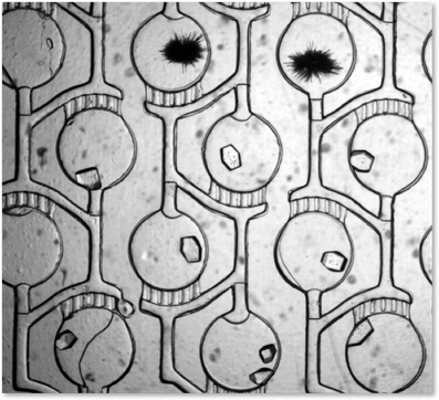
Liquid – liquid phase boundary of a PEG / ammonium salt mixture. In Figures 5b, c and d three images are shown of a single drop as water flows out and the solutes concentrate. Two wells, similar to the well shown in Figures 5b,c and d, are shown in this 24 hour time lapse movie. The drop starts out in the single phase region (Figure 5b). As the drops shrink they take on a bluish tinge as the dye is concentrated. At a certain point there is a sudden flash as the liquid-liquid phase boundary is crossed. Note that both drops cross the phase boundary simultaneously. As the drop further shrinks, the proportion of the dense liquid phase increases. Video: Jung Uk Shim.
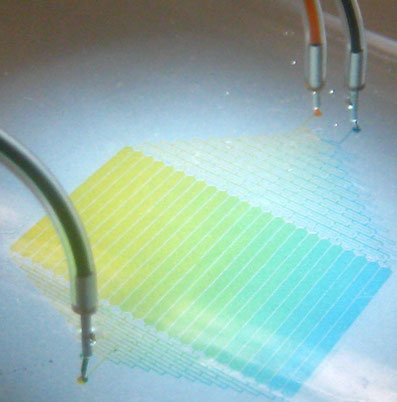
Chemical potential reservoir used in video to right. It generates a linear gradient of 12 different salt concentrations.
Photo: Šeila Selimovic
Phase Chip Storage. Channel width: 100 microns, Height: 50 microns. Water drops in dodecane. 2 micron diameter colloids in water for flow visualization. Drops surfactant stabilized with Span80. Geometry: long channels with wells of greater depth located to size. Drops lower surface energy by entering well and reducing oil/water surface area by deforming shape. High speed photography: speed slowed down by 100x - you just see a blur when imaging by eye in microscope.
Phase Chip chemical potential. A crystal of xylanase is alternately grown and dissolved by varying the contents of the reservoir. The xylanase (Hampton Research, HR7-104), was dialyzed against 0.4M potassium sodium tartrate tetrahydrate (Hampton Research, Crystal Screen HR2-110) and the initial protein concentration was 15.3 mg/ml. Xylanase does not crystallize under these conditions. When the reservoir contains high salt, water flows out of the protein solution, dehydrating the protein solution and the crystal grows. When the reservoir contains low salt, water flows into the protein solution and the crystal dissolves. This demonstrates the ability of the Phase Chip to control crystal growth. Timelapse: 12 hours. Video: Jung Uk Shim.

Liquid-liquid phase separation in a mixture of lysozyme and PEG in the Phase Chip. This is a 2-layer chip made out of PDMS. Protein/PEG drops are located in the upper plane and are separated from the salt reservoirs by a PDMS membrane that is only permeable to water. The reservoir on the left (R3) has a lower salt concentration than the reservoir on the right (R4). The one on the right undergoes liquid-liquid phase separation, while the one on the left does not. Posts in the reservoir layer prevent collapse of the membrane and are separated by 100 microns. Video: Šeila Selimovic